A PCB DFM Checklist Helps You Pass a Design Review
Once you’ve completed a complex design and sent your data to your manufacturer, your design will be pored over by one or more engineers. These folks go through new designs looking for anything that could reduce fabrication and assembly yield, or that creates a risk of rework or a failed board. When you’re trying to get to market quickly, the last thing you need is for your board to receive no-bid status.
Anything that appears as a discrepancy between design files, Gerber files, netlist data, and your BOM should be addressed before manufacturing. Some design choices can cause your board to receive no-bid status. Your new board won’t hit the fabrication line until all aspects of the design have passed these important checks and sign-offs are complete. Before you send your board off for manufacturing, you should complete an in-house design review if you want to cut down the time required to put your board into production. We’ve compiled a PCB DFM checklist that helps ensure your board will be fully manufacturable, testable, and sourceable.
What’s in Your PCB DFM Checklist?
A PCB DFM Checklist needs to account for all aspects of manufacturability. You’ll need to check that basic DFM rules are followed throughout your board. Normally, your design software should help spot common DFM problems before you finish your design. However, there are some electrically functional design choices that your software will allow you to implement, yet these design choices will be difficult or impossible to manufacture.
Perhaps the most common DFM mistakes that are electrically correct include:
- Pads or traces connected directly to copper pour. This is an electrically correct design choice, meaning it will not affect the electrical functionality of your board. In some cases, such as with unique RF routing strategies, this is actually beneficial, but it is difficult to address during manufacturing. This design choice is a common cause of tomb-stoning. A large copper region will create uneven heating during reflow soldering, which leads to tomb-stoning.
- Overlapping drill hits.If you need to route a slot for your board, you should not place overlapping holes in your layout as this will cause drill bits to break during manufacturing. High quality design software will flag this as a design rule violation, and your manufacturer can spot this in your Gerber files. Instead, you can explicitly define this region as a slot in your design data.
- Missing solder mask between pads or holes.During reflow soldering, the solder mask acts like a dam that holds a solder ball on the desired pad. If the solder mask is absent between pads, molten solder can easily flow between two neighboring pads and create a bridge. In BGAs with a dog-bone fan-out to a via, absent solder mask will allow solder to wick through the via to the inner layer, possibly creating a short.
- Component spacing.Components and connectors should not be arranged too closely in a layout as this can cause problems for pick-and-place machines. Once placed on a board during assembly, a bulky component or connector may block the next component that needs to be placed. Similarly, closely spaced.
- Drill bit sizes.It’s best to opt for a smaller number of drill bit sizes whenever possible as this cuts down on board fabrication costs.
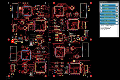
Fixing these important design points can be as simple as turning on all your layers in your design software when running through a PCB DFM checklist. The other important DFM aspects that your manufacturer will check are shown below.
Be sure to turn on all layers during your internal layout review to spot missing solder mask.

Add Design File Inspection to Your PCB DFM Checklist
Any manufacturer that is worth their costs should include the following areas in a PCB DFM checklist. As a designer, it’s useful to keep these points in mind before you send your design out for production. The last thing you need is a series of redesigns, or to receive no-bid status. In addition to the common points listed above, designers and manufacturers should keep the following points regarding design files on their PCB DFM checklist:

Reference Designators in Your BOM, Layout, and Schematics
Your bill of materials can contain a number of critical mistakes, both from a sourcing perspective and from a design synchronization perspective. A key part of a PCB DFM checklist is to compare manufacturer’s part numbers supplied by customers with the component description. In addition, reference designators in the schematic, layout, and bill of materials should be compared to ensure there are no mismatches. Your netlists, specifically an IPC-D-356 netlist, should also be compared with the schematic netlist, your board’s Gerber data, and your component reference designators. Reference designator mismatch between a bill of materials, netlists, a layout, and schematics are quite common in new designs requiring collaboration across a large team.
Acid Traps
Acid traps are often discussed in the context of right-angle PCB traces, but newer etchants have alleviated this problem in 90-degree routing. However, traces routed to pads at acute angles can still be an acid trap simply due to the small space in a corner. The etchant can get trapped in a corner due to surface tension when traces are routed to pads at acute angles, as shown below. Instead of doing this, route straight to the pad rather than make the connection at an angle. Your manufacturer can spot and correct acid traps with a Gerber viewer application.
Your manufacturer can spot things like acid traps with a Gerber viewer.

Component Sourcing
If you have supply chain visibility tools available in your design software, you can consider sourcing components yourself. At minimum, you should look into the supply chain to ensure your components are available in the quantities you need and that they will not go EOL soon. PLDs, unique SoCs/r SoMs, and other rare components can be quickly located simply by going directly to the component manufacturer or authorized distributor. This allows designers to determine scalability for a new design or whether replacement components should be used. Ideally, this should be done as early as possible in the design process. As part of a PCB DFM checklist, you can cut down PCB design review time by listing acceptable alternative parts in your bill of materials.
The other important aspect of preparing for manufacturing is design for testability (DFT). These points are a subset of those typically discussed in DFM, and this subject is extensive enough to warrant its own article. I’ll present the central tasks and ideas in an upcoming piece, including how you can plan your design for different testing processes and equipment.
If you need a PCB design firm that can ensure your next build will be fully manufacturable, look no further than PCBLOOP. We’ll develop a DFM checklist for your new product and help you get through the manufacturing process. Contact PCBLOOP today for a consultation.
Thiѕ web site really has all of the information I wanted about this subject and didn’t know who to ask.
Hello Hardwood, thank you for your interests to our site.
What specific stuff do you want?
You can request it by sending us a message over https://www.pcbloop.com/contacts/
Or sending us an email at support@pcbloop.com
Thank you for your support.
Hola! I’ve been reading your website for some time now and finally got
the bravery to go ahead and give you a shout out from Dallas Texas!
Just wanted to mention keep up the good work!
Thank you for your comments
Its such as you learn my mind! You seem to know a lot about this,
such as you wrote the book in it or something.
I think that you could do with some percent to force the message house
a bit, however instead of that, that is magnificent blog.
A great read. I’ll definitely be back.