Before assembly, the factory will check ambiguous design files. The Assembly files you provided may not be complete. Such as no designator in the silkscreen, silkscreen not complete and not clear, no orientation in the silkscreen, centroid file is not complete, no pick and place file, pick and place file can not match with the silkscreen, and so on.
1.No silkscreen in ambiguous design file, no assembly drawings or pdf file, no centroid file(pick and place file)
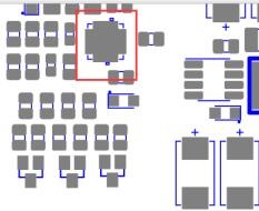
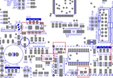
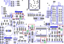
2. silkscreen drawing is in a mess which can not be identified
before read: The Best High Speed Board Design Guidelines
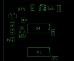
3. No designator on silkscreen
4.Factory can not assemble when there is no designator in the centroid(pick and place) file. Suggestion: please provide complete centroid files, including XY data and designator.
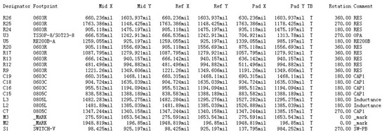
5. Pick and place files for the top and bottom sides together, which confuses the factory doing the assembly.
Suggestion: please provide a pick and place file separately for each layer, then this will be more clear for assembly.
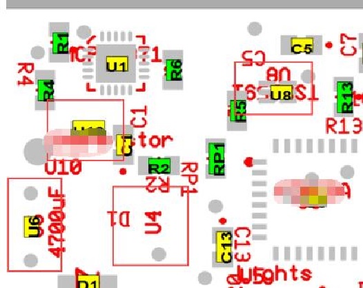
6. No polarity mark for polarity components. Suggestion: It’s better to add “+” “-” marks on PCB. Please add polarity cathode or anode mark and pin 1 in the silkscreen layer.
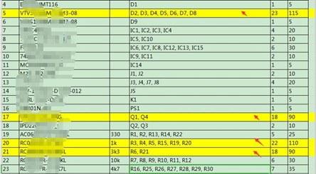
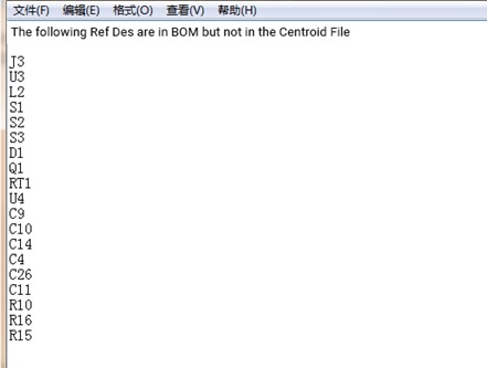
7.the Total number of designators in the Centroid file is different from what is in the BOM. Some designators are included in BOM, but not in the centroid file. Suggestions: 1. please verify if some designators in the BOM are not needed to solder 2. please confirm if the centroid file is correct.
The Total number of designators in the Centroid file is different from what is in the BOM. Some designators are included in BOM, but not in the centroid file. Suggestions: 1. please verify if some designators in the BOM are not needed to solder 2. please confirm if the centroid file is correct.7. the Total number of designators in the Centroid file is different from what is in the BOM. Some designators are included in BOM, but not in the centroid file. Suggestions: 1. please verify if some designators in the BOM are not needed to solder 2. please confirm if the centroid file is correct. Wo7. the Total number of designators in the Centroid file is different from what is in the BOM. Some designators are included in BOM, but not in the centroid file. Suggestions: 1. please verify if some designators in the BOM are not needed to solder 2. please confirm if the centroid file is correct.
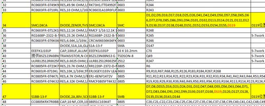
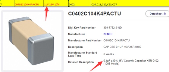
8. Normally, we buy components that follow the part number in the BOM, but the value that you wrote is not the same as the value of the part with that part number. Suggestions: 1. please check the value in the BOM is correct or not 2. please check whether the part number is correct.
9. The quantity of designators is not the same as the data shown in the “quantity” column in the BOM. Suggestion: please check the exact part quantity then update the BOM accordingly.
![]()
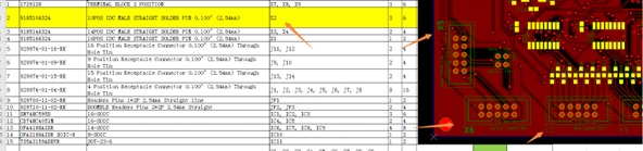
10. The designator in the BOM cannot match the silkscreens on the boards. For example, the designator in the BOM is X2, however, the silkscreen is X6. Suggestion: please correct the wrong designator in the BOM.
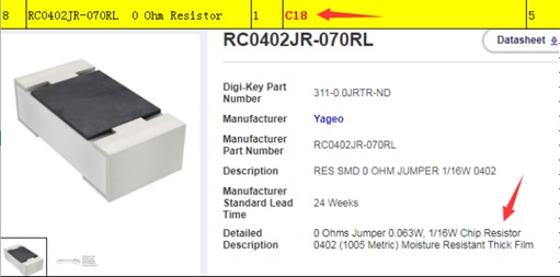
11. In the general naming convention, C means Capacitor, and R is Resistor. If the component is a resistor, but you name it with C, it will confuse us. If you can name the capacitor with the beginning of C, and the resistor with the beginning of R, it will be much better.
12. In the BOM, if no color requirements for LED, we cannot confirm which LED color you want. We also cannot confirm whether the part is right or not when the color requirements on BOM are different. Suggestion: write correct parameters in the BOM like the LED color, brand, and package.
13. It’s not normal for the designator to be repeated in the BOM. If only one existing designator, we suggest to delete the extra repeated designator OR correct the designator in the BOM.